13
stages, in order

Free resource
The order things actually have to happen in, and the check that proves each step before you move to the next. Written for a board that has never booted - your first dev kit or a custom design.
Get the printable PDFOnly have a Raspberry Pi or a dev kit? Stages 05, 08, 09 and 10 are your practice path — finish them and you have a real bring-up story to tell in an interview.
The checklist
Bring-up goes wrong in a predictable way: a stage is assumed good, the next stage fails, and the debugging happens in the wrong place. A board that reaches U-Boot but hangs entering Linux is usually a DDR (main memory) or a device-tree problem, not a kernel problem. So each stage below carries the observation that proves it before you move on. If you cannot produce the proof, you have not finished the stage.
Before power
The reference design is the only configuration the vendor has actually booted. Every deviation is a thing you will debug later, so write the deviations down now while they are cheap to find.
The SoC has a required order and timing for its supplies. Out-of-order rails can leave the part in an undefined state that looks exactly like a dead chip.
The boot ROM cannot run without its input clock. This is a five-minute check that saves days.
Stages 01 to 03 above are complete. Enter your email and we send the full 13-stage checklist, laid out to print.
No mailing list, no spam. By email we send the file once and stop.
First signs of life
The boot ROM is masked silicon and cannot be changed. Your job is to make it find a valid image on a medium it is configured to read.
4 checks, the proof and the failure modes — in the full checklistEnter your email for the full version →Until you have a console you are debugging blind. Everything after this stage depends on it.
DDR is the stage that produces the most confusing downstream failures, because a marginal memory system does not fail cleanly. It corrupts.
4 checks, the proof and the failure modes — in the full checklistEnter your email for the full version →Want all 13 stages, with the proofs, at the bench? Get the printable checklist ↓
Into the bootloader
A working prompt means DDR, clocks, console and storage stack are all healthy enough to be scripted against.
4 checks, the proof and the failure modes — in the full checklistEnter your email for the full version →This is the handoff. Most first-boot failures here are the device tree describing a board that does not exist.
4 checks, the proof and the failure modes — in the full checklistEnter your email for the full version →Into Linux
A shell prompt is the boundary between bring-up and development. Get there on the simplest possible rootfs first.
4 checks, the proof and the failure modes — in the full checklistEnter your email for the full version →Bring peripherals up individually. Enabling everything at once turns one failure into an unreadable log.
4 checks, the proof and the failure modes — in the full checklistEnter your email for the full version →After the first boot
At this point the board boots because of a sequence of manual steps. None of that is reproducible until it is written down as build inputs.
4 checks, the proof and the failure modes — in the full checklistEnter your email for the full version →This decision sets your security position for the life of the product, and it is hard to reverse late.
4 checks, the proof and the failure modes — in the full checklistEnter your email for the full version →The remaining work is what separates a board that boots from a product you can ship and support.
4 checks, the proof and the failure modes — in the full checklistEnter your email for the full version →What it leads to
If you are learning, this section is a preview of the judgment the job pays for.
Stage 12 is the one with consequences beyond bring-up, and it takes ten minutes to do properly. Find the kernel series your BSP pins (uname -r on the running board, or the tag in the vendor tree), then look it up on the kernel.org releases page, which publishes the projected end-of-life for every longterm series. Write that date next to the life you expect the product to have; any gap between the two is engineering work someone has to own. Stage 13 runs into the CRA reporting obligations that begin on 11 September 2026.
The complete version, laid out to print and keep. Sent once.
No mailing list, no spam. By email we send the file once and stop.
Questions
Related tools and resources
 Read free + printable PDFEmbedded Linux GlossaryBSP, DTB, SBOM - the acronyms that fill docs, forum posts and reviews, decoded. 25 terms with the misunderstanding corrected: a BSP treated as a kernel, an SBOM produced by scanning.Open →
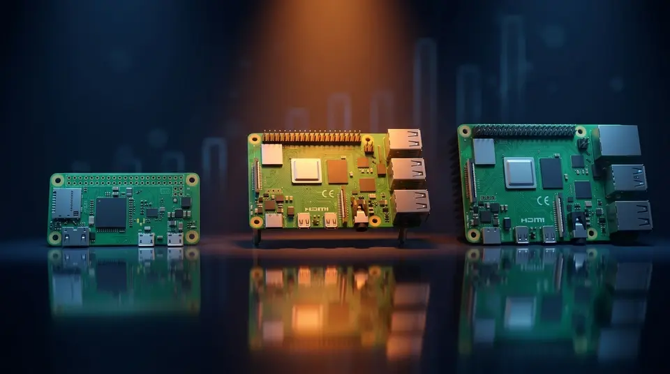 Free guideChoosing Your First SBCWhich board fits what you want to build - learning Linux internals, home automation, vision, robotics. Matched by use case, with the four checks before you buy.Open →
 Live once a monthFree monthly masterclassOne free hour, live, every month, with a working kernel engineer. Bring your questions - including the one about how to get into this field. Recordings stay on YouTube.Open →
 Free career guideCareer roadmapsWhich skills stay in demand as AI spreads, and the order to learn them - for the embedded Linux and kernel paths.Open →